ACP’s switches (COM) follow the same configuration as the potentiometers, as shown in previous sections of this catalogue. The word COM needs to be added to the description. The cells 5, 6 and 7 (value, taper and tol) are left blank. If the switching angle is different from our standard, then it should be indicated.
Examples:
From CA9: COMCA9MH2,5 2DT SNP PI WT-9005-BA (switch in configuration CA9MH2,5 with 2 detents, terminals with snap in, wiper at CCW position, and white shaft reference 9005 already inserted).
| Potentiometer model | With shaft or thumbwheel inserted? | pieces per small box (150 x 100 x 70) | Pieces per bigger box (250 x 150 x70, CG on description) |
|---|---|---|---|
| H2,5 - V2,5 - V5 - VS5 - HSMD - VSMD - VESMD | None, only potentiometers. | 1.000 | 4.000 |
| 6001, 6030, 6032, 6035, 6037 | 1.000 | 3.000 | |
| 6024, 6025, 6028 | 300 | To be determined. | |
| 6022, 6023, 6031 | 500 | To be determined. |
Example: Standard Features
| Series | Rotor | Model | Packg. | Ohm value | Taper | Tolerance | Life | |
|---|---|---|---|---|---|---|---|---|
| 1 | 2 | 3 | 4 | 5 | 6 | 7 | 8 | |
| COM | CA9 | M | H2,5 | - | - | - |
Example: Extra features
| Track | Collector | Terminals | Housing | Rotor | Wiper position | Linearity |
|---|---|---|---|---|---|---|
| 9 | 10 | 11 | 12 | 13 | 14 | 15 |
| 2DT | SNP | PI |
Example: Assembled Accesory
| Assembly | Ref# | Color | Flam. |
|---|---|---|---|
| 16 | 17 | ||
| WT | -9005 | -BA |
Example: Standard features
| Series | Rotor | Model | Packg. | Ohm value | Taper | Tolerance | Life | |
|---|---|---|---|---|---|---|---|---|
| 1 | 2 | 3 | 4 | 5 | 6 | 7 | 8 | |
| COM | CA14 | P | V15 | - | - | - |
Example: Extra features
| Track | Collector | Terminals | Housing | Rotor | Wiper position | Linearity |
|---|---|---|---|---|---|---|
| 9 | 10 | 11 | 12 | 13 | 14 | 15 |
| AC45º±15º |
Example: Assembled accessory
| Assembly | Ref# | Color | Flam. |
|---|---|---|---|
| 16 | 17 |
Electric Function
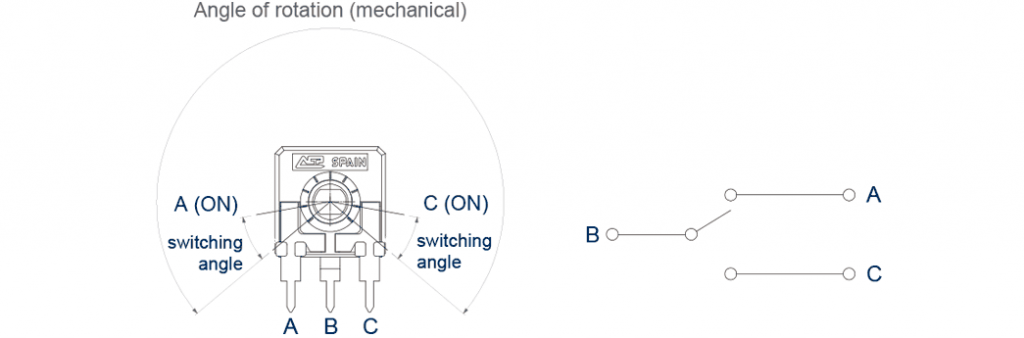
The three terminals of the potentiometer are equivalent to one input (B) and two outputs (A and C), as shown in the figure. The middle terminal (B) corresponds to the internal wiper, which switches between positions. The switching angle can be customized.
Unless otherwise requested, the housing will be neutral color, with the marking in black.
Electric Specifications
| COM CA6 | COM CA9 / MCA9COM CA14 / MCA14 | COM CE9 / MCE9COM CE14 / MCE14 | |
|---|---|---|---|
| Resistive element | Carbon | Carbon | Cermet |
| Power ratio | 15V / 12mA | 24V / 12mA | 24V / 12mA |
| Resistance at ON position | ≤5Ω | ≤5Ω | ≤5Ω |
| Dielectric Strength | 600V | 1500V | 1500V |
| Insulation resistance | 100MΩ | 100GΩ | 100GΩ |
| Switching angle at ON position | 20º ± 15º | 30º ± 15º | 30º ± 15º |
| Operating temperature | -25ºC... +70ºC (+85ºC) | -40ºC... +90ºC (+125ºC) | |
| Please, note that these are standard features; other specifications are available on request. | |||
Mechanical Specifications
| 6mm | 9mm | 14mm | |
|---|---|---|---|
| Angle of rotation | 235º ± 10º | 240º ± 5º | 265º ± 5º |
| Mechanical life | 1.000 | 1.000 | 1.000 |
| Wiper torque | < 2 Ncm | < 2 Ncm | < 2.5 Ncm |
| Max. stop torque | 4 Ncm | 5 Ncm (CA9, CE9)25 Ncm (MCA9, MCE9) | 10 Ncm (CA14, CE14)15 Ncm (MCA14, MCE14) |
| Max. push/pull on rotor | 9.8 N | 40 N / 50 N | 40 N / 50 N |
