Electric use
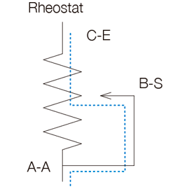
Variable resistor
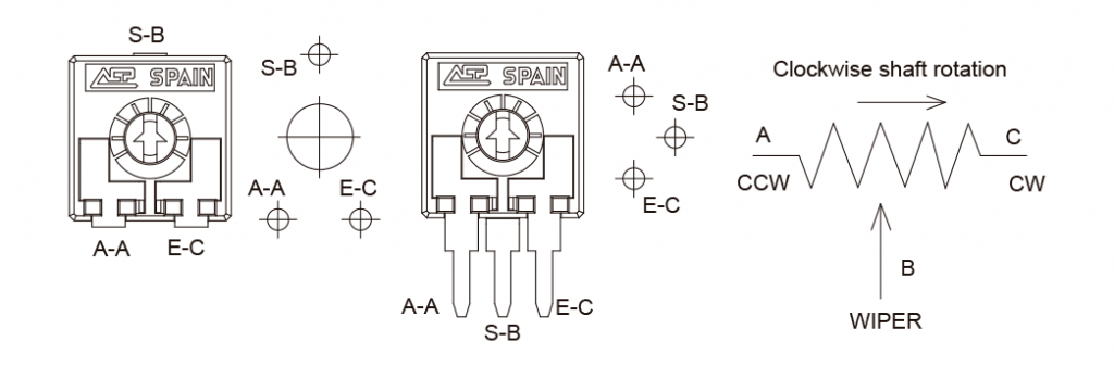
When pins A and B or C and B are connected, the current goes through the wiper (blue line).
Depending on where in the resistor the wiper is placed, it indicates
a lower resistive value than the whole resistor would (we say it is used as variable resistor or rheostat).
The output is measured in ohms.
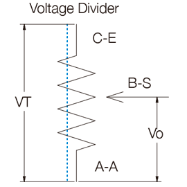
Voltage divider
When a voltage is applied between the ends of the resistor (A and C), the current goes through the resistor, not the wiper.
The wiper sees a proportional share of the voltage applied between the ends (we say this is a Voltage Divider).
The output is a voltage, measured in V.
Resistance
Total resistance (RT):
It is the resistance found between the input terminal and the wiper when the latter is positioned to give the maximum value.
Electric noise or contact resistance (RC):
Noise is any variation in the output signal that does not correspond to a similar variation in the input signal. It appears in the contact point between the resistive element and the wiper. It is measured in Ohms.
This noise can also be measured as “contact resistance variation” (CRV), which is expressed in the percentage of change between the initial resistance and the value of the resistance after a test. It is measured statically and dynamically. ACP’s potentiometers have less than 5% CRV.
ACP’s standard resistive values
The standard values are as follows, although values out of range can also be studied.
| 100Ω | 200Ω | 220Ω | 250Ω | 470Ω | 500Ω | 1KΩ | 2KΩ | 2.2KΩ | 2.5KΩ | 4.7KΩ | 5KΩ | 10KΩ | 20KΩ | 22KΩ |
|---|---|---|---|---|---|---|---|---|---|---|---|---|---|---|
| 100 | 200 | 220 | 250 | 470 | 500 | 1K | 2K | 2K2 | 2K5 | 4K7 | 5K | 10K | 20K | 22K |
| 25KΩ | 47KΩ | 50KΩ | 100KΩ | 200KΩ | 220KΩ | 250KΩ | 470KΩ | 500KΩ | 1MΩ | 2MΩ | 2.5MΩ | 4.7MΩ | 5MΩ |
|---|---|---|---|---|---|---|---|---|---|---|---|---|---|
| 25K | 47K | 50K | 100K | 200K | 220K | 250K | 470K | 500K | 1M | 2M | 2M5 | 4M7 | 5M |
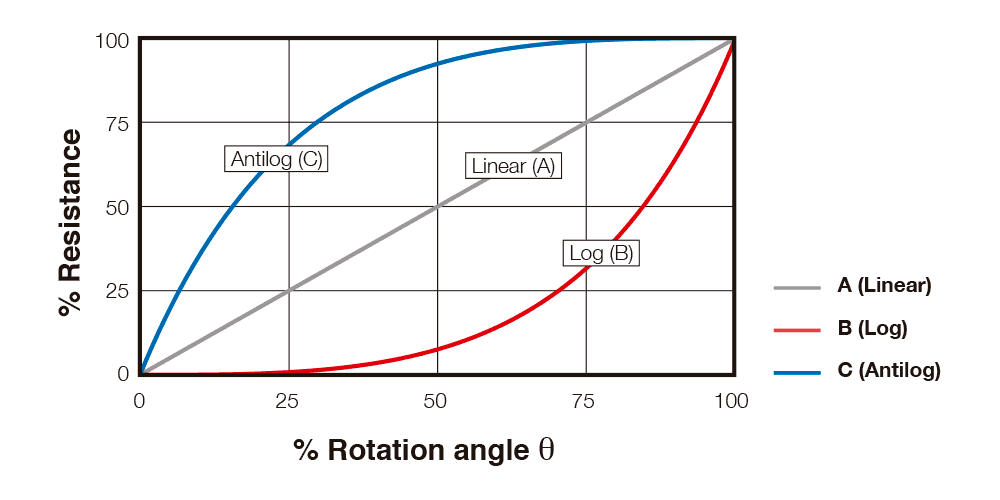
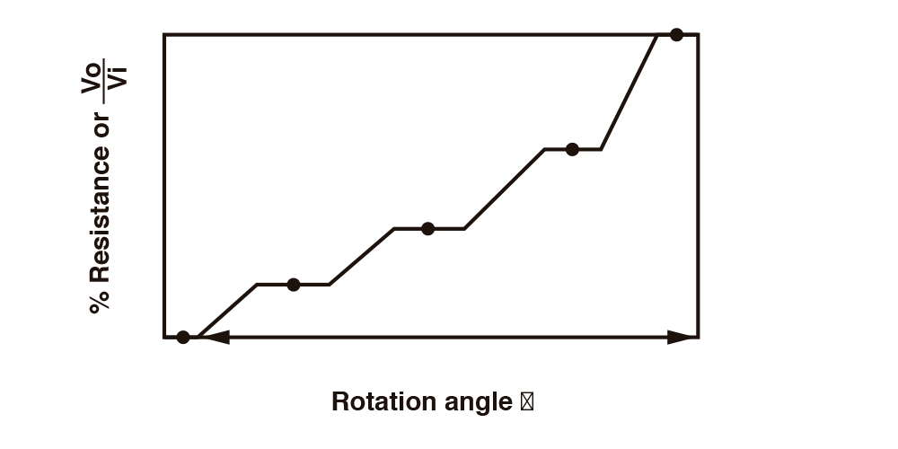
Variation laws - Tapers -
The standard taper is linear (A). Log (B) and Antilog (C) tapers are also available, as well as special tapers according to customer’s specifications. For example, a special taper can be matched with a potentiometer with detents (click effect), to guarantee a value in a specific position – see bellow.-
ACP can also provide with tapers with different slopes, with areas with constant value or jumps, according to customer’s specifications.
Special tapers can be combined with physical detents to match the areas where the customer wants to guarantee a constant value with a particular angular position. This is particularly suitable in applications which can benefit from a feeling of maintained control over the position, for example, regulation of temperature or speed.
REGULAR TAPERS
SPECIAL TAPERS
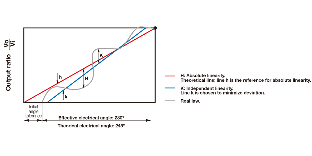
Linearity
The term “linearity” implies that the real law obtained from plotting angular position vs voltage output is compared with a straight line.
Independent linearity (LN)
It is the maximum vertical deviation of the real law from the straight reference line chosen to best minimize the distance from the real line in any position.
It is expressed as a percentage of the total voltage applied.
In the graph below, “K” would be the maximum independent linearity and “k” the line with which the real law is compared.
Absolute Linearity (LA)
It is the maximum vertical deviation of the real law from the straight reference line that runs through specified minimum and maximum points.
These points would be zero and 100% of the maximum applied voltage.
In the graph below, “H” would be the maximum absolute linearity of the real law and “h” the theoretical line with which the real line is compared. When some customers are looking for correspondence of angle and value, this is the concept to consider.
Recommended soldering conditions
Soldering conditions (Lead free, RoHS compliant)*
| Manual Soldering | Reflow soldering SMD | Flow (wave) soldering |
|---|---|---|
| Soldering tools of 20W max. | Preheating temperature: Max 150ºC; 60-90 s | Recommended Alloy: SnAgCu |
| Maximum temperature of soldering tools: 280ºC | Temperature Ramp-up: 2-3ºC / s. | Preheating stage: Max 100ºC; 30-60 s. |
| Time: 3 s. max. | Over 220ºC:<40 s. | Temperature Ramp-up:1.2-2.5ºC/s. |
| Solder temperature: 240ºC for 5 ± 1 s. | Max. wave temp.: 260ºC for 4s., (245ºC recommended) | |
| Besides recommended conditions,ACP SMD potentiometers have successfullypassed IEC 60068-2-58 tests. | Time within +0º-10ºC of peak: 10s. | |
| Cooling rate: 5ºC/s. | ||
| (*) For other information on soldering conditions, please, contact us. | ||
